COMET - Cost-efficient Open-Source Multicopter for Embedded-Systems Teaching
3D-Print Guide
This guide covers the pre-print calibration, materials and settings, printing steps, and post-processing of the COMET frame and its accessories.
Find the needed files here:
- Slicer projects (recommended to use): mechanical/prints/
- Meshes (STL): mechanical/exports/stl/
- Interchange solids (STEP): mechanical/exports/step/
Naming of the 3MF projects inside the slicer project folders:
- Clearance gauge for pre-print calibration:
clearance-gauge-*.3mf - A single print plate is used for all COMET frame parts:
frame-*.3mf - Non-functional colored parts:
color-coding-*.3mf
Table of Contents
Clearance Gauge Calibration
To achieve precise hole clearances, flat first layers, and accurate dimensions, calibrate the printer with the intended filament. For more information, consult the manufacturer’s manual or look into these helpful sources:
Printer calibration is only effective to a certain extent, and some tolerances still remain. This step attempts to address the remaining uncertainty through the proper selection of clearances. This repository provides a test print part to determine the necessary clearance values for threaded inserts, M2 and M3 screws, and frame parts to ensure a proper fit. The source can be found in the mechanical/source/tools folder, named clearance_gauge.FCStd. We recommend using it for the frame print, and it is optional for color-coded parts.
Fig. P-1. The clearance gauge printed in PC CF on our research group's Prusa CORE One 3D printers
1) Print the Clearence Gauge
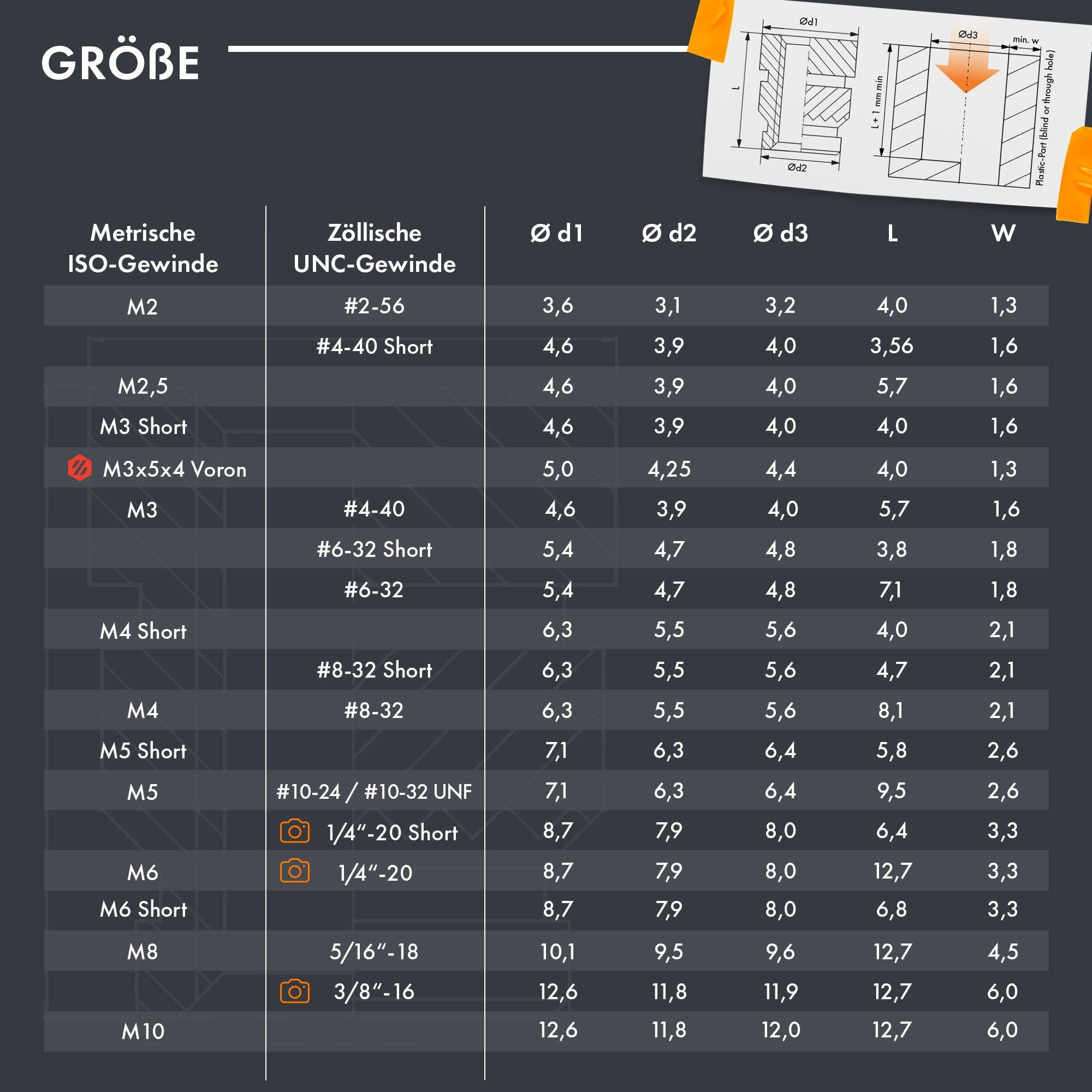
First, find the outer and knurl diameters (threaded_insert_outer_diameter and threaded_insert_knurl_diameter in the parameters file) and minimum wall thickness (threaded_insert_minimum_thickness in the parameters file) of the M3 threaded inserts on the manufacturer’s datasheet (example), or measure them with calipers. Enter these values into lines L12, L13, and L14 in section “[1] Pre clearance gauge test values” of the part’s parameter file mechanical/source/part_parameters.yaml.
To proceed, apply the current part parameters and ensure that all exports and slicer projects are up to date by using the following commands in the cloned repository’s root folder:
freecad.cmd -c scripts/apply_parameters.py
freecad.cmd -c scripts/export_source.py
Print the clearance gauge using either the 3MF project clearance-gauge-*.3mf from a supported slicer and printer setup (look into mechanical/prints/), OR use the exported STL or STEP files (look into mechanical/exports/) to set up your own project.
2) Determine Clearances
Once the print is complete, take one threaded insert, one M2, and one M3 screw (the length of the screws does not matter) from the ordered parts. Use the clearance gauge to determine which clearance your printer and filament combination needs for each part category, and note these values down for later.
Insert each part into the corresponding test hole one at a time. Each “row” is a different test, and the “columns” represent increasing clearance values in millimeters from left to right. Aim for a smooth, non-loose fit for the clearance holes and a firm, pressable fit for the insert pilots.
Fig. P-2. Testing the smooth side of the threaded insert in row 1 (top left), the knurled side of the threaded insert in row 2 (top right), the fit of the M3 screws in row 3 (bottom left), and the fit of the M2 screw through hole in row 4 (bottom right).
The last test is for fitting the rotor arms together with the landing gear mount to form the landing gear of COMET. This is the only occasion where 3D prints are put together, so care must be taken. A small rotor arm test piece is included in the clearance gauge and can be broken off. Try inserting this piece into the square holes that emulate the landing gear mount. Again, aim for a smooth, non-loose fit. Note this clearance value as well.
Fig. P-3. Testing the fit and clearance of the rotor arm and landing gear mount.
3) Update the Project
Use the resulting values and change lines L21, L23, L25, and L27 in section “[2] Values based on clearance gauge results” of the part’s parameter file mechanical/source/part_parameters.yaml. You may want to adjust the value of the elephant_foot_chamfer parameter in line L4 to compensate for a potentially remainig elephant foot in your prints. This value determines the size of the chamfer applied to the bottom of every 3D-printed part.
Again, apply the current part parameters and ensure that all exports and slicer projects are up to date by using the following commands in the cloned repository’s root folder:
freecad.cmd -c scripts/apply_parameters.py
freecad.cmd -c scripts/export_source.py
Everything is now ready to print with proper clearances.
3D Printing
Pre-dry the filament: PC is highly hygroscopic. Before printing, ensure your Filament Dryer is set to 80\text{ }\text{\textdegree C} and dry the spool for 4 to 6 hours.
Use 3MF projects in hardware/mechanical/exports/3mf/ or follow manifest.csv. STL/STEP are in hardware/mechanical/exports/{stl,step}/. Follow docs/printing.md for materials, orientation, and post‑processing.
0) ensure that 3D printer calibration for elephant foot and over-/under-extrusion is done!
- See the section Printed Parts for material and settings.
- Follow instructions
- STL and 3MF files are in hardware/exports/ and hardware/prints/3mf/.
- See mechanical/prints/README.md for recommended materials, orientations, and slicer profiles.
- Download STL/STEP: mechanical/exports/{stl,step}/
-
Optional: use provided 3MF projects for a known-good profile.
-
Verify printed parts match dimensions (critical hole diameters, arm thickness).
- Recommended materials:
- PC-CF or ABS for the drone’s frame (separte 3mf project file)
- PETG for color-coding/cosmetic parts (separte 3mf project file)
- Baseline settings (see part notes and screenshots in docs/printing/):
- Nozzle: 0.4 mm
- Layer height: 0.2 mm (first layer 0.3mm)
- Perimeters: 4
- Top Solid layers: 6
- Bottom Solid layers: 6
- Infill: 20% Gyroid
- Cooling: minimal for PC‑CF/ABS (just enough for bridges); normal for PETG
- Orientation: each STL is oriented “as printed”
- Slicer profiles:
Provided 3MF projects for PrusaSlicer in hardware/prints/3mf/ with per‑category settings. - Heat‑set inserts: sizes and temperatures in part notes (docs/printing/) - README.md
-
Post‑processing in hardware/prints/README.md (threaded inserts); post‑processing (reaming, tapping, heat‑set insert temperatures); removal of support.
- Files:
- Editable: hardware/freecad/parts/*.FCStd
- Interchange: hardware/exports/step/*.step
- Mesh: hardware/exports/stl/*.stl
- Slicer projects: hardware/prints/3mf/
Printed parts
- See ../../hardware/mechanical/exports/stl/ and manifest.csv for settings
-
Recommended materials: PC/CF (frame), and PETG (color-coding parts) 2) Verify filament profile, nozzle, layer height, and cooling match the baseline above or the embedded profile. 1) Print parts according to manifest and 3MF projects. 2) Install heat-set inserts (where specified).
- Use the 3MF projects to capture intended orientation, supports, and modifiers.
- Typical settings (starting point; see manifest.csv for part-specific):
- Nozzle: 0.4 mm; Layer: 0.20 mm
- Walls: 4; Top/Bottom: 6; Infill: 35-50% (gyroid) for arms
- Material: PC/CF-Nylon
- Tolerances (rule of thumb):
- Write values in params/default.yaml
- Test coupons: test/coupons/ includes hole ladders and insert gauges.
Quality checks after printing
- Critical thickness (arms/plates) within ±0.2 mm of nominal.
- M3 fasteners pass freely through clearance holes after light reaming (if needed).
- No layer splits, especially near screw bosses and arm roots.
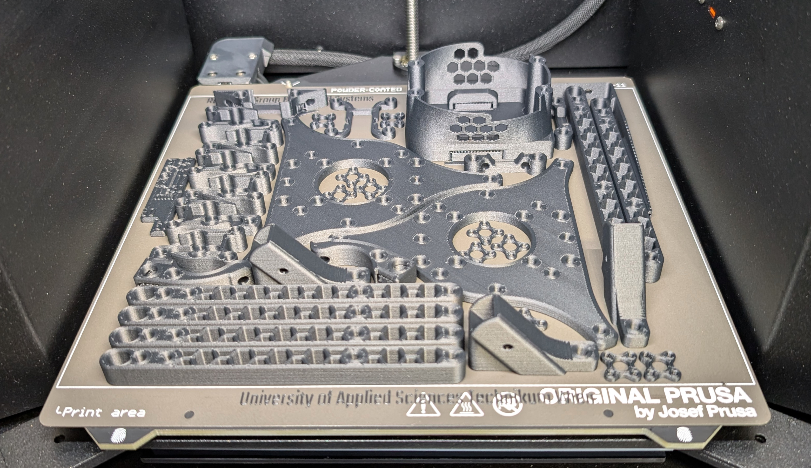
Fig. P-4. The finished 3D-printed frame parts were produced using our research group's Prusa CORE One 3D printers. This build plate contains all the (functional) parts needed to assemble COMET.
Post-Processing
The final step is post-processing, which involves removing the supports and applying the threaded inserts. For the latter, gather all of the ordered threaded inserts together.
Important note: Wear PPE (a respirator/dust mask and nitrile gloves) during this step, as glass and carbon fiber dust can splinter from the parts and become airborne, entering your skin and lungs. If possible, avoid sanding or scraping the parts, as this can increase the probability of particles becoming airborne.
1) Correct Print Defects
Take a good look at the 3D-printed parts, e.g., check the general quality and look for layer separations. You can find a list of potential print defects and how to fix them here. Severe defects may require printing some part again.
2) Remove Support
3D printing often requires support structures that hold the molten plastic in position during printing (e.g., for overhangs). The placement, density, and size of these supports often vary depending on the slicer software and print settings used. This results in different supports that need to be removed.
In order to further process the printed parts, those supports must first be removed. The parts of concern are the battery holder (BH-01), the RC receiver mount (RC-01), and the ESC connector mount (YF-04). These supports can be broken off by applying a small amount of force with a nose plier.
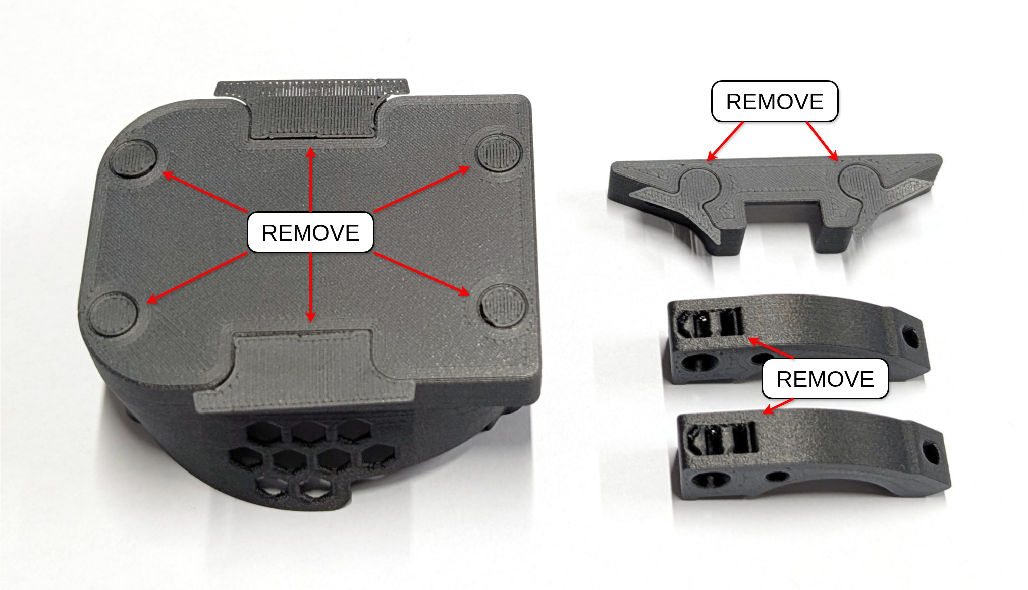
Fig. P-5. Shows places where supports need to be removed (based on PrusaSlicer).
3) Apply the Threaded Inserts
- Use brass heat‑set inserts matching the BOM (typically M3).
- Procedure: 1) Support the part on a flat surface. Align the insert square to the hole. 2) Heat the insert, press gently until the flange sits flush or to the modeled depth. 3) Keep light downward pressure while removing heat to avoid pull‑out. 4) Let cool fully; do not thread a screw while warm.
- Tips:
- If an insert sits proud, reheat briefly and seat further. Do not force cold.
- If the pilot is too tight, touch the rim with a deburring tool before insertion.
- Use the provided insert gauge coupon in test/coupons/ to validate fit and temperature.
a) Preparation of the Landing Gear Mounts
Threaded inserts will be used throughout the build for easier assembly. These inserts are melted into the 3D-printed parts using a soldering iron with optional melting-aiding tips (see the tool list). If you have never worked with these type of threaded inserts before, this tutorial video may be helpful. A note on the video: We achieved the best results with a temperature 15°C above the 3D printing temperature. For example, PC CF is printed at 290°C; therefore, the temperature should be set to 305°C. After setting the correct temperature, align the threaded inserts (LG-03) with the holes in the rotor arms (LG-02) and landing gear mounts (LG-01).
THREE times
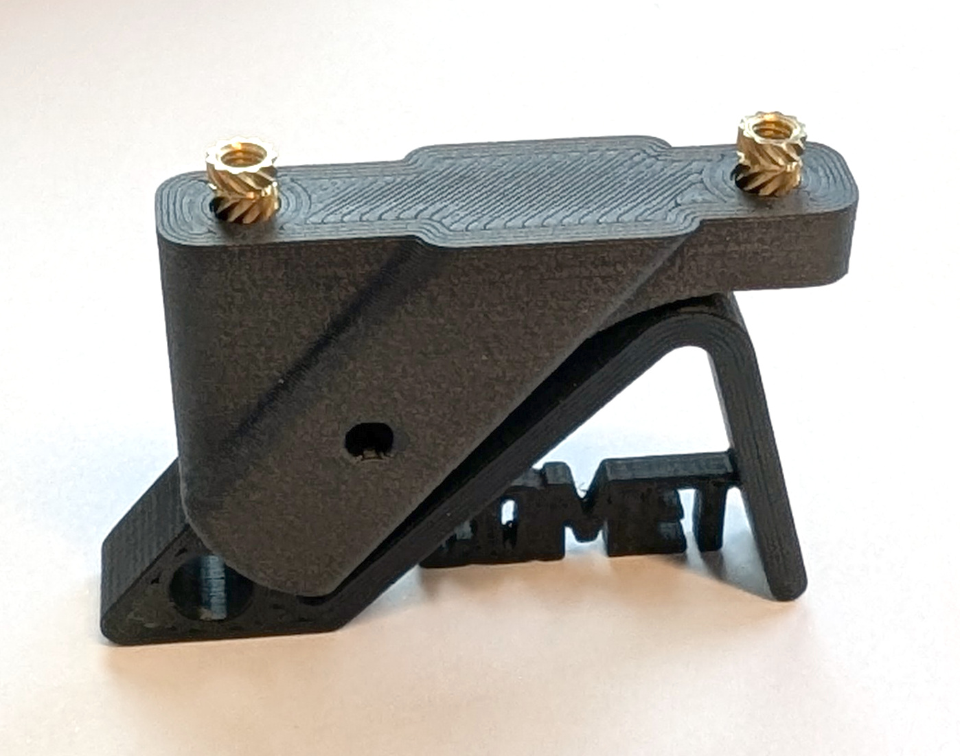
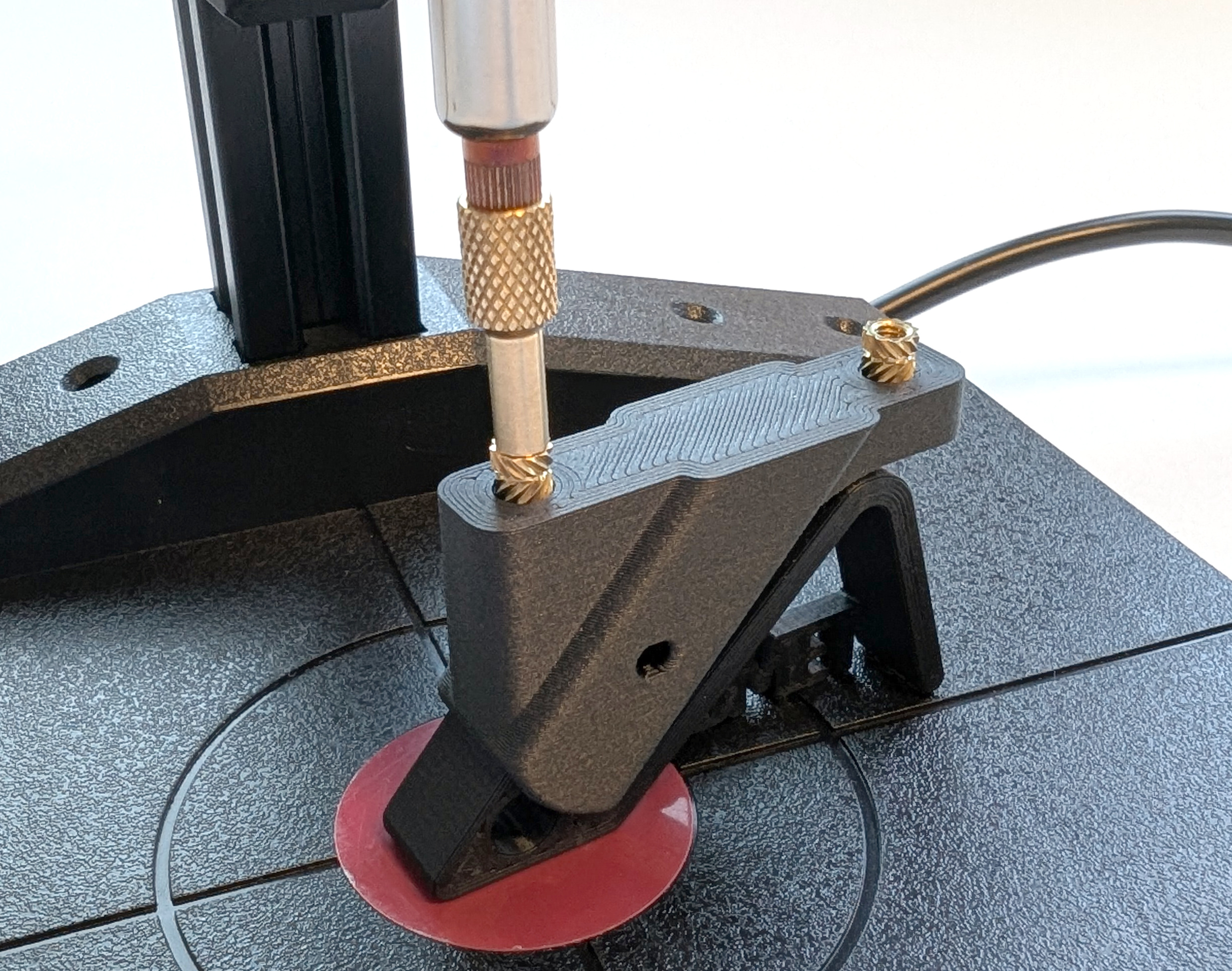
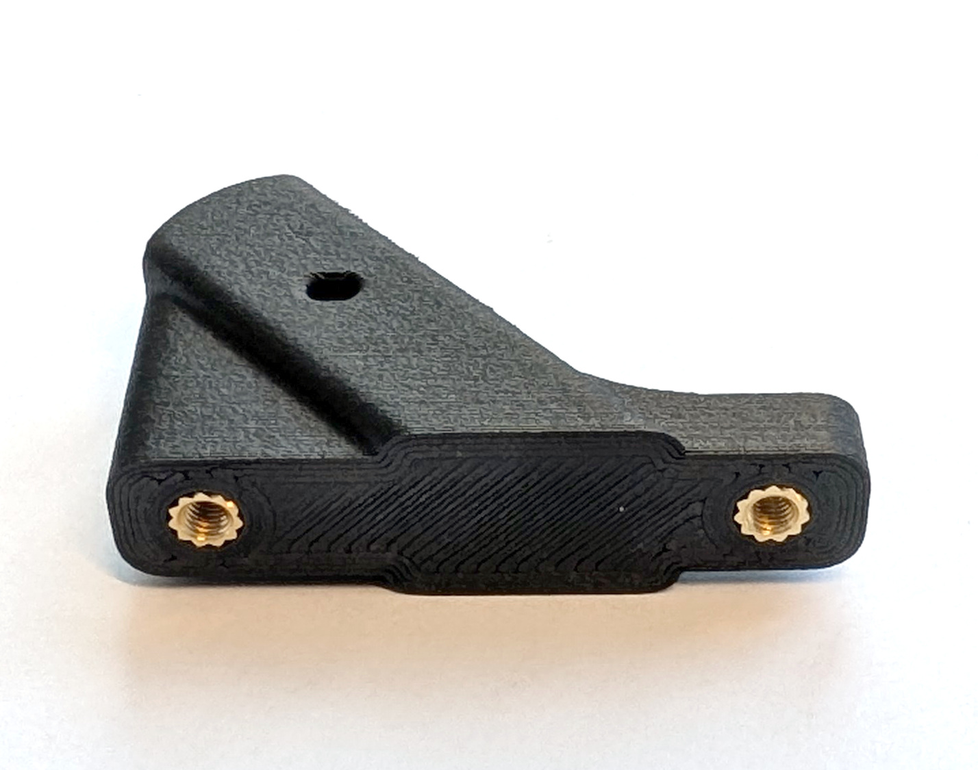
Fig. 27. The images show how to best align the threaded inserts for the landing gear mount (left), how to best apply the heat through the soldering iron (middle), and the finished preparation of the landing gear mount (right). Repeat each step three times for the full landing gear set.
b) Preparation of the Rotor Arms (Landing Gear Legs)
Hold the soldering iron tip against the insert. Once the insert is heated up, push it into the part until it is flush with the surface. During this procedure, keep the soldering iron perpendicular to the surface to ensure the inserts are not at an angle. Note that the inserts and the surrounding plastic will get hot and need to cool down.
THREE times
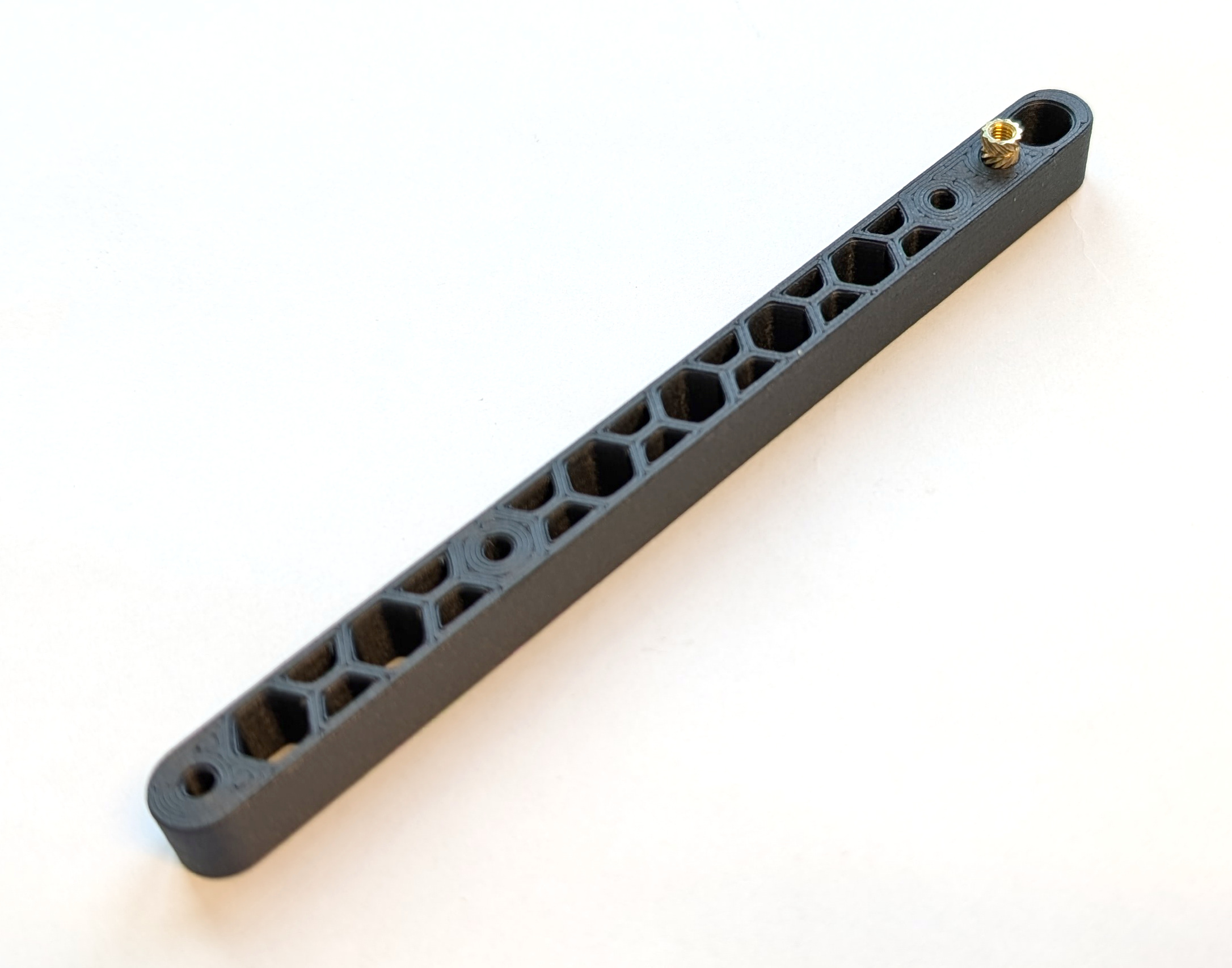
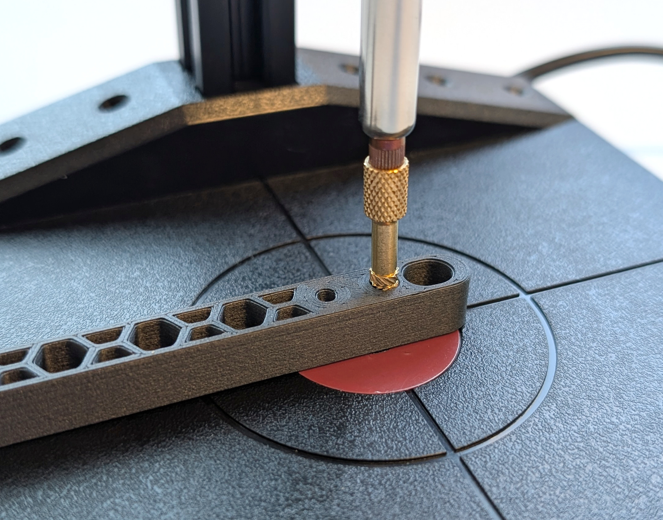
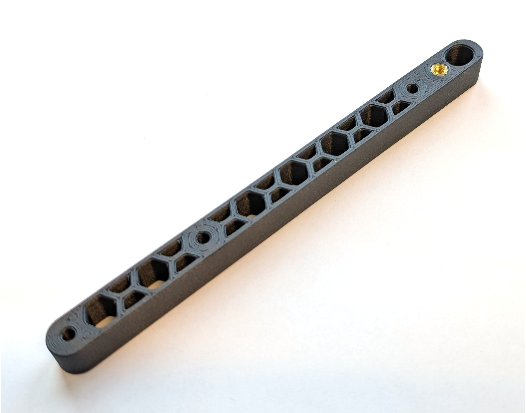
Fig. P-X. The images show how to best align the threaded inserts for the rotor arm (left), how to best apply the heat through the soldering iron (middle), and the finished preparation of the rotor arm (right). Repeat each step three times for the full landing gear set.
c) Preparation of the Battery Holder
To prepare the battery holder (BH-01) for assembly, melt the two thread inserts (BH-02) into the holes to the left and right of the text “COMET.” Again, ensure that the inserts are perpendicular to the surface and that the correct temperature is selected (e.g., PC CF at 305°C).
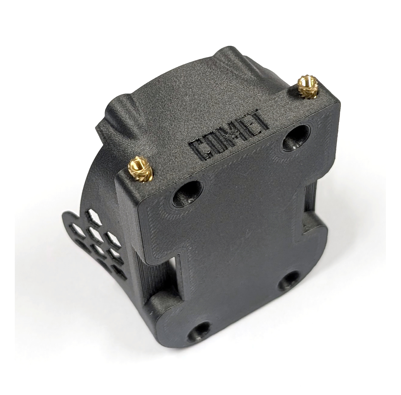
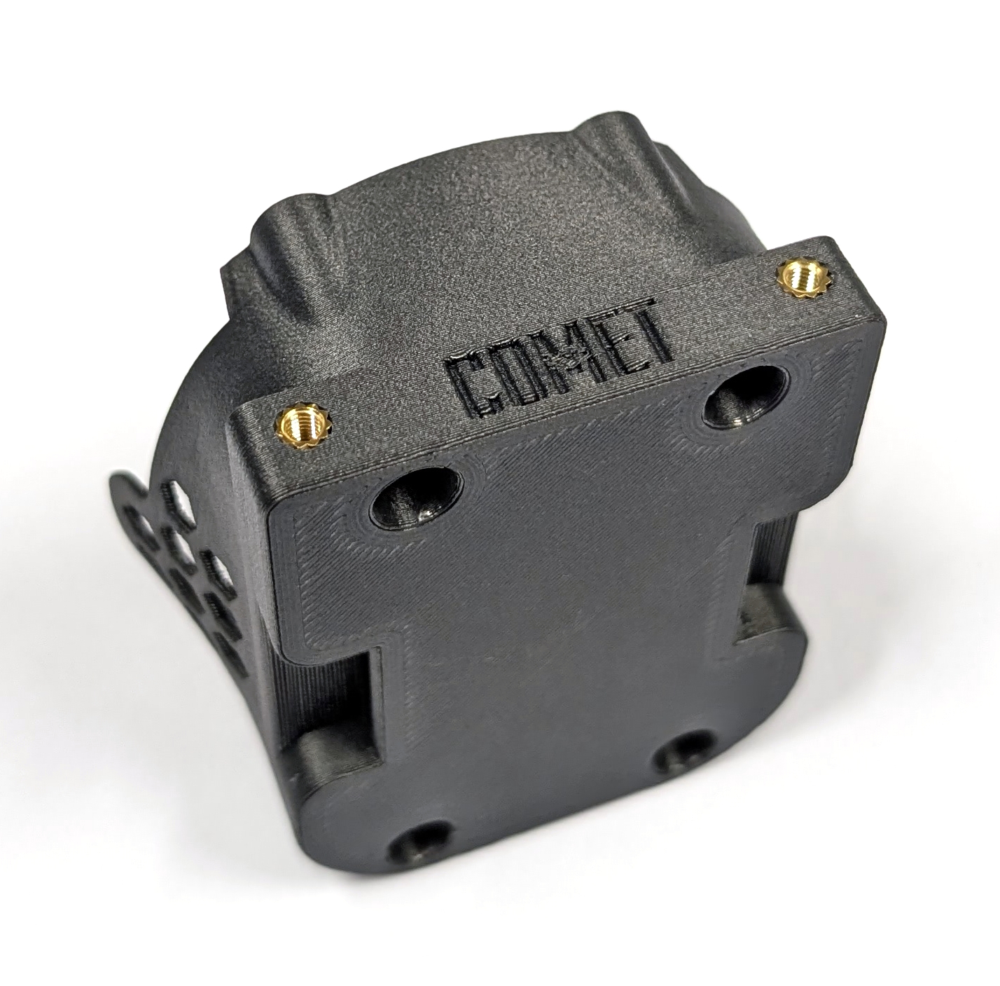
Fig. 32. Preparation of the thread inserts (left) and finished preparation of the battery holder (right).
d) Preparation of the Mounting Plate
As with the landing gear, begin by melting the thread inserts (YF-06) into the bottom mounting plate (YF-01, only one piece), the XT30 connector mount (YF-03), the ESC connector mount (YF-04), and the quick release base (YF-05). Ensure the thread inserts are perpendicular to the surface and the right temperature is selected (e.g., PC CF 305°C).
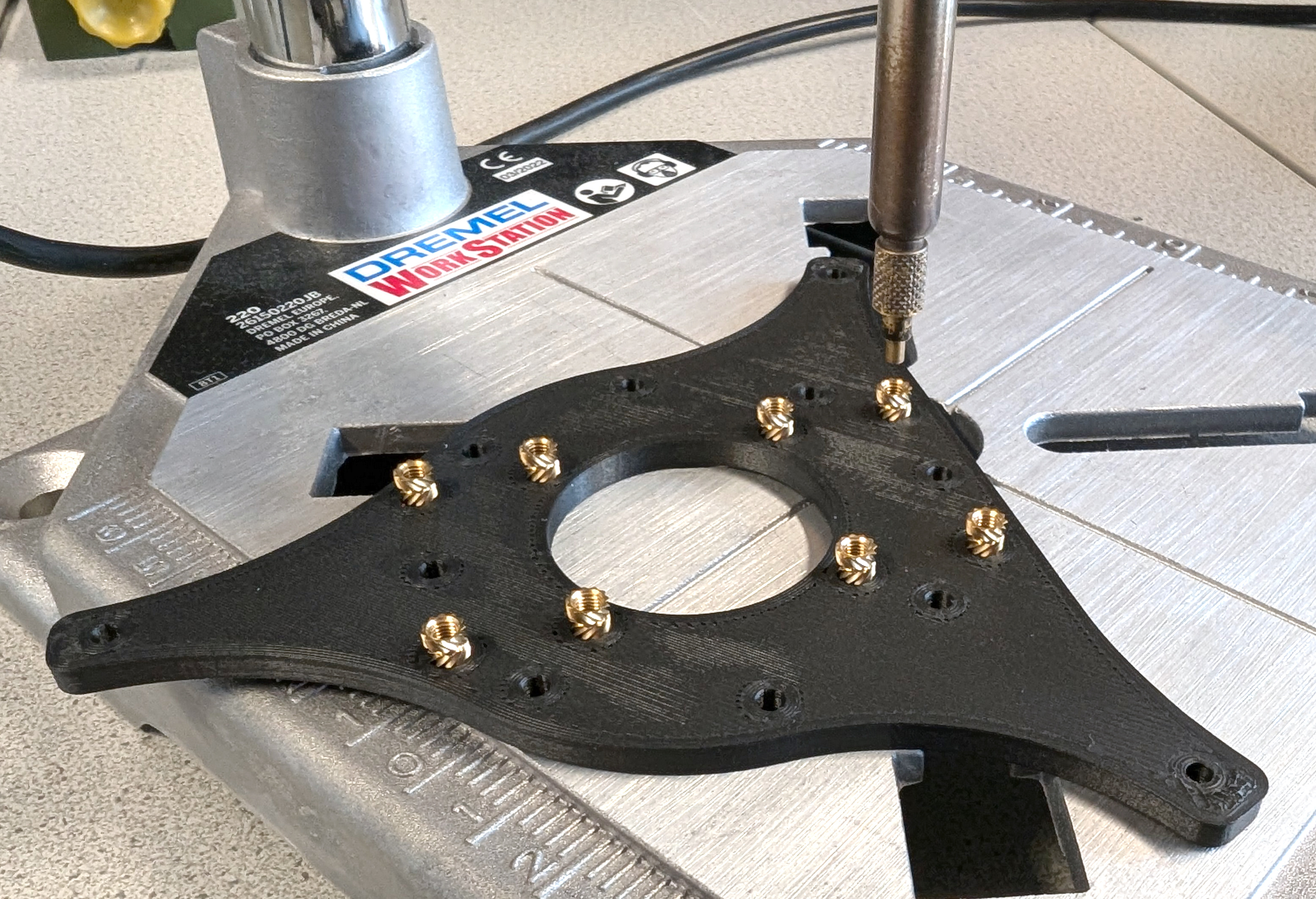
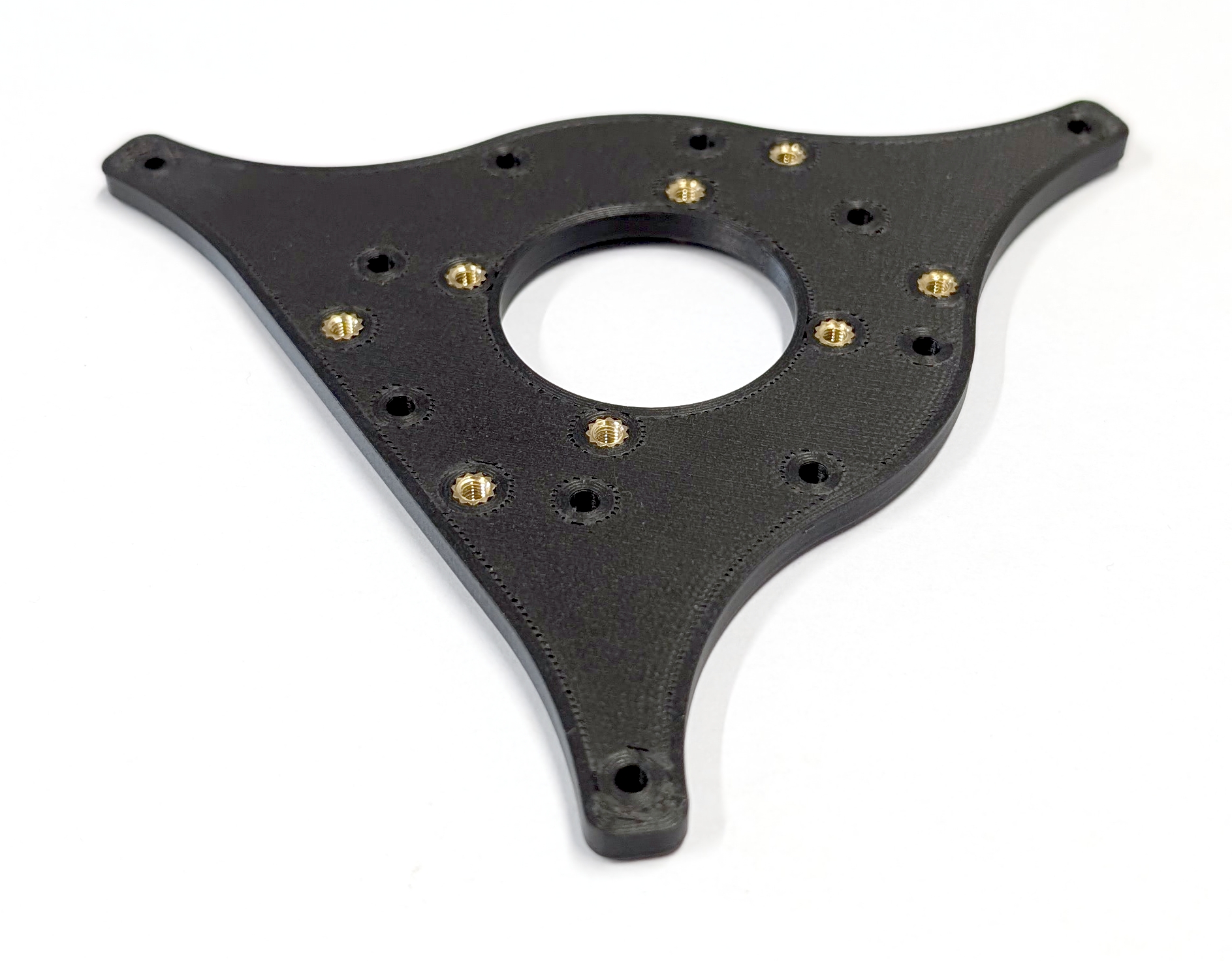
Fig. 40. Example of how to best align the thread inserts for the bottom mounting plate (left). Prepared bottom mounting plate. All inserts should be flush with the bottom surface (right).
e) Preparation of the XT30 Male Connector Mounts
TWO times
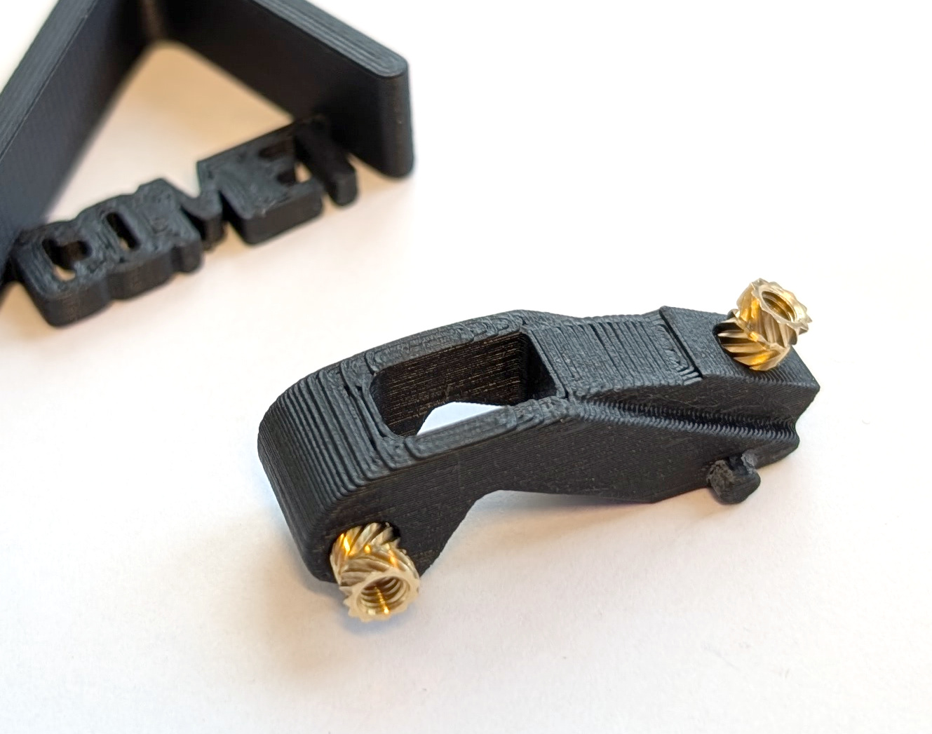
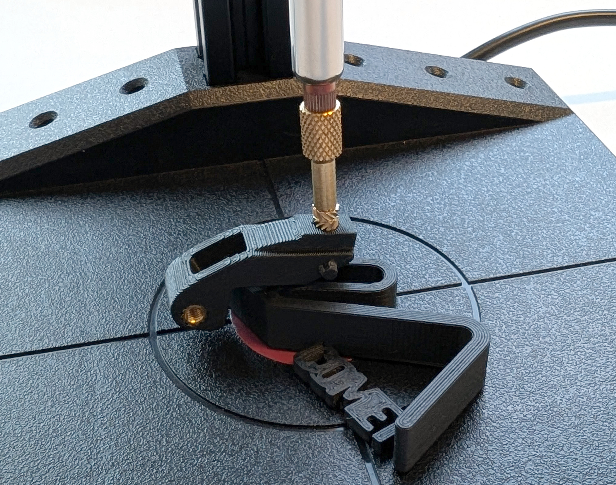
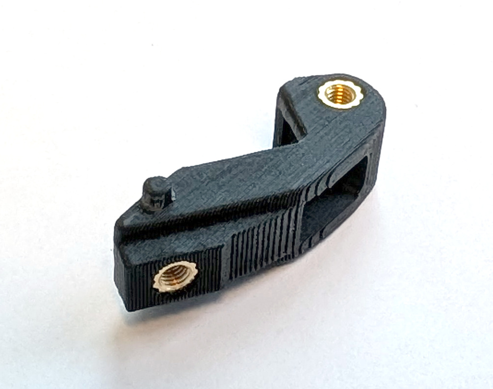
Fig. 27. Examples of how to best align the thread inserts for the landing gear mount (left), how to apply the force with to threaded insert (middle), and the finished preparation of the landing gear mount (right).
f) Preparation of the Quick Release Bases
TWO times
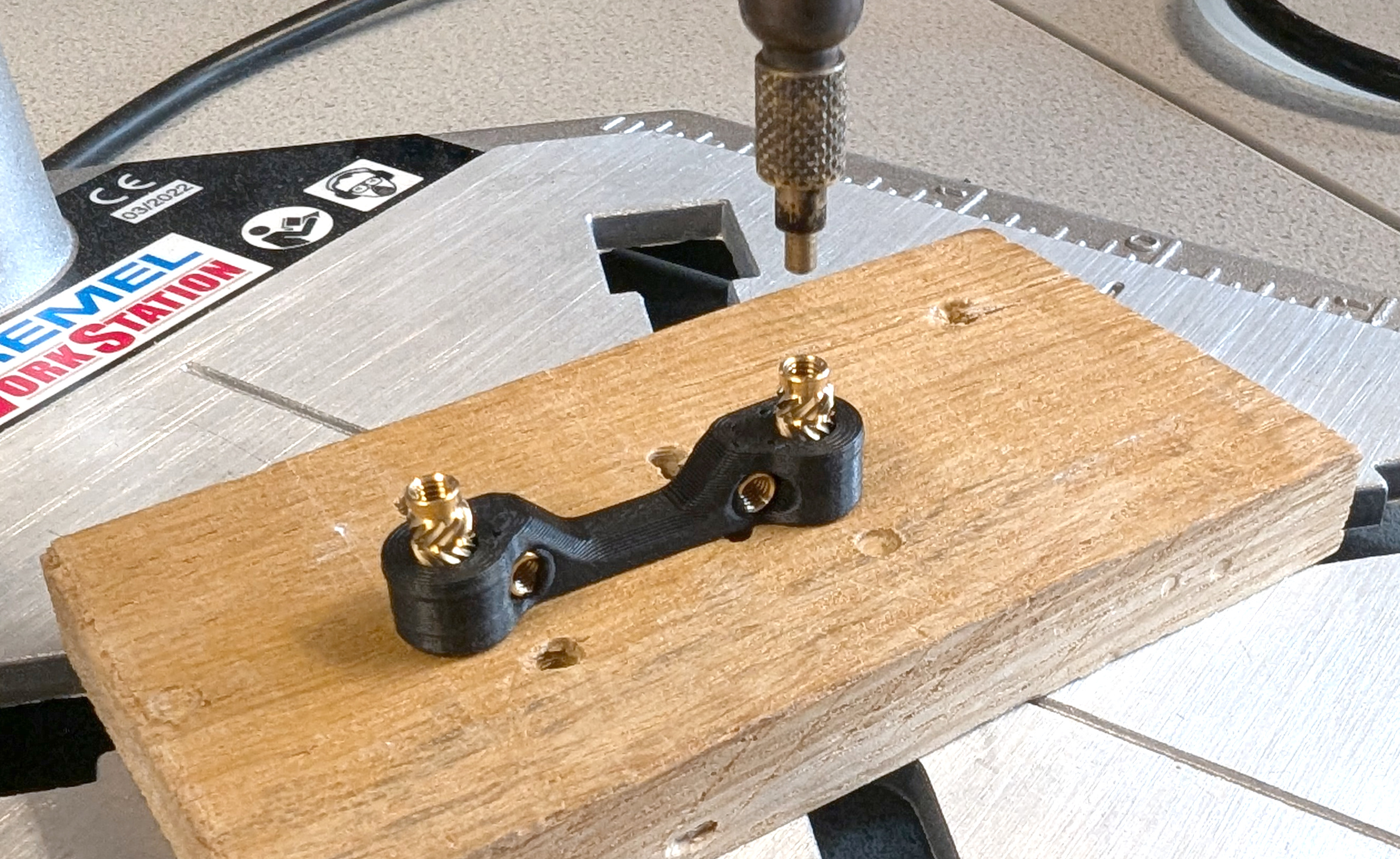
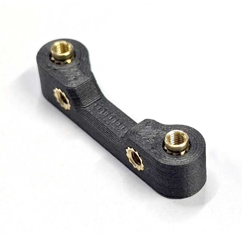
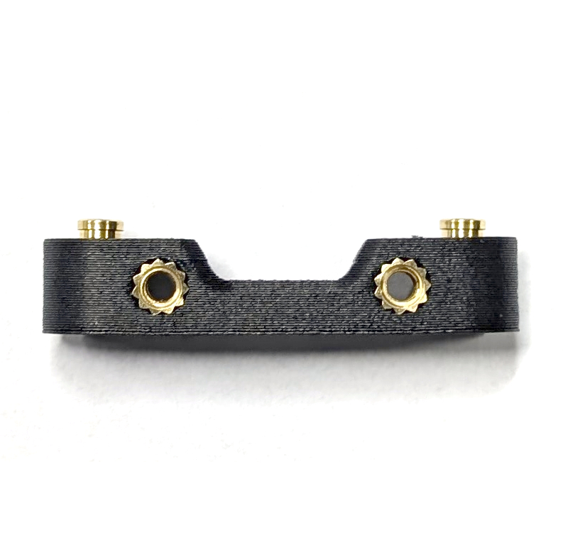
Fig. 43. Example of how to align the thread inserts for the quick release base (left) correctly. Prepared quick release bases (middle) and a detailed look at the inverse thread inserts (right).
g) Preparation of the ESC Connector Mount
The ESC connector mount (YF-04) and the quick release bases (YF-05) have thread inserts that face the mounting plates turned upside down. This ensures proper alignment of the components when they are mounted to the mounting plate. As illustrated in the figures, insert them into the holes upside down (with the smooth part of the insert facing up) and push them in until the knurl is in the component. The smooth surface should stick out.
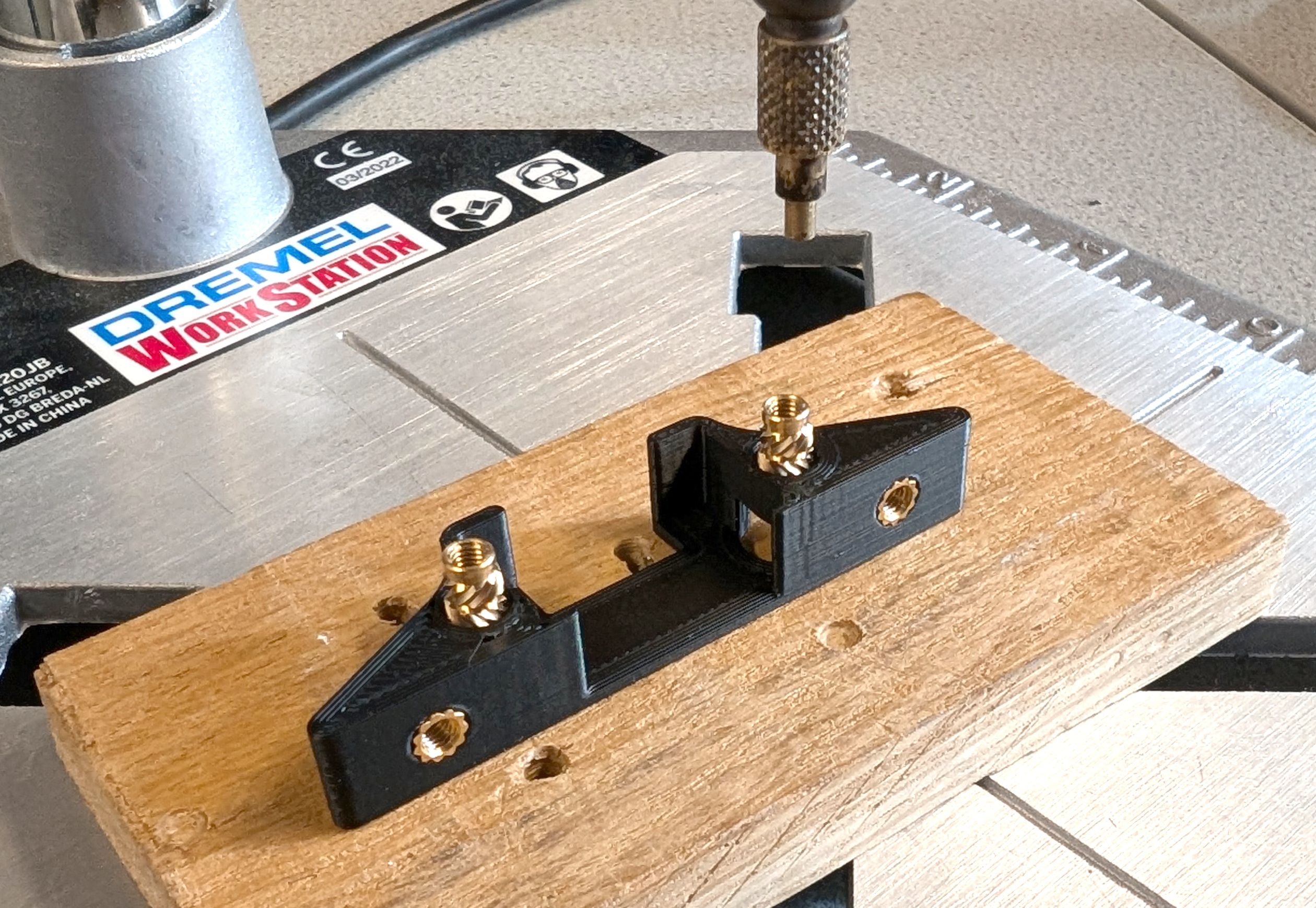
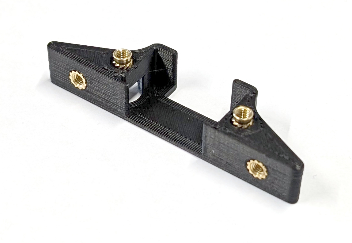
Fig. 42. Example of how to best align the thread inserts for the ESC connector mount (left). Prepared ESC connector mount (right).
Next Step
Assemble COMET using the build manual in docs/build.md.